2003 Nissan Altima Ignition Switch Diagram
Fuse box diagram (fuse layout), location, and assignment of fuses and relays Nissan Altima SE, S/S, SE-R (L31) (2002, 2003, 2004, 2005, 2006).
Checking and Replacing Fuses
Fuses and fusible links protect your vehicle's electrical system from short-circuiting or overloading. If electrical parts in your vehicle are not working, the system may have been overloaded causing a blown fuse. Before you replace or repair any electrical parts, check the appropriate fuses.
- Be sure the ignition switch is pushed to the OFF or LOCK position and all switch are OFF.
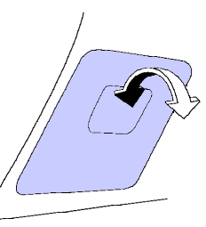
- Open the fuse box lid.
- On the fuse diagram, find the number of the fuse you want to check. The diagram tells you where to locate the fuse on the panel. Pinch the fuse perpendicularly with the fuse puller and pull it out.
- To check a fuse, look at the silver-colored band inside the fuse. If the band is broken or melted, replace the fuse with a new one.
- If a new fuse also opens, have the electrical system checked and repaired by a Nissan dealer or a repair facility of your choice.
- If any electrical equipment does not operate and fuses are in good condition, check the fusible links.
Notice
- Never use a fuse of a higher or lower amperage rating than that specified. This could damage the electrical system or cause a fire.
- Never replace a broken fuse with anything other than a new fuse (such as wire, foil, etc). Use always an intact fuse of the same color.
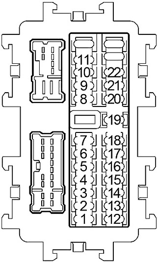
Passenger Compartment Fuse Box
The fuse panel is located behind the lid on the driver's side of the dashboard. Pull the fuse box cover to remove.
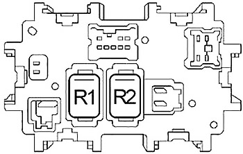
Back side
| № | A | Circuit Protected |
|---|---|---|
| 1 | 10 | Engine Control Module, Injectors, Immobilizer Control Unit (2001-2002), Body Control Module (BCM (2003-2006)) |
| 2 | - | - |
| 3 | - | - |
| 4 | - | - |
| 5 | 15 | Power Socket |
| 6 | 10 | 2001-2002: Audio, Body Control Module (BCM), Door Mirror Remote Control Switch |
| 10 | 2003-2006: Audio, Body Control Module (BCM), Door Mirror Remote Control Switch, AV Switch, Combination Meter, Display Control Unit, NAVI Control Unit, Triple Meter, Satellite Radio Tuner | |
| 7 | 15 | Cigarette Lighter |
| 8 | 10 | Door Mirror (LH, RH) |
| 9 | 10 | Engine Control Module (2001-2002), Daytime Running Lights |
| 10 | 15 | Blower Motor, A/C Auto Amplifier (2001-2002), Front Air Control (2003-2006) |
| 11 | 15 | Blower Motor, A/C Auto Amplifier (2001-2002), Front Air Control (2003-2006) |
| 12 | 10 | 2001-2002: Automatic Speed Control Device (ASCD) Brake Switch, Data Link Connector, Daytime Running Lights, Starter Relay, Shift Lock Control Unit, A/C Auto Amplifier, Thermo Control Amplifier, Body Control Module (BCM), A/C Control Unit, Combination Switch, Heated Seat Relay, Rear Window Defogger |
| 10 | 2003-2006: Automatic Speed Control Device (ASCD) Brake Switch, ASCD Clutch Switch, Body Control Module (BCM), Display Control Unit, Data Link Connector, Daytime Running Lights, Front Air Control, Headet Seat Relay, NAVI Control Unit, Park Neutral Position Switch, Rear Window Defogger Relay, Starter Relay, Shift Lock Control Unit | |
| 13 | 10 | Air Bag Diagnosis Sensor Unit, Occupant Classification System Control Unit (2003-2006) |
| 14 | 10 | Combination Meter, Park Neutral Position Switch, Auto Dimming Inside Mirror, Back-Up Lamp Switch (Manual Transmission (2003-2006)), Triple Meter (2003-2006) |
| 15 | 15 | 2001-2002: Heated Oxygen Sensor |
| 16 | - | - |
| 17 | 10 | 2003-2006: NAVI Control Unit |
| 18 | - | - |
| 19 | 10 | 2001-2002: Transmission Control Module (TCM), A/C Auto Amplifier, Homelink Universal Transceiver, Security Indicator Light, Key Switch, Key Lock Solenoid, Combination Meter, Body Control Module (BCM), Trunk Room Lamp, Data Link Connector |
| 10 | 2003-2006: Combination Meter, AV Switch, Display Control Unit, Data Link Connector, Front Air Control, Homelink Universal Transceiver, Security Indicator Light, Shift Lock Control Unit, Transmission Control Module (TCM), Triple Meter, Vanity Mirror Lights | |
| 20 | 10 | Stop Lamp Switch |
| 21 | 10 | 2003-2006: Automatic Transmission Device, Body Control Module (BCM), Key Switch, Key Lock Solenoid, Shift Lock Control Unit |
| 22 | - | - |
| | ||
| R1 | Blower | |
| R2 | Accessory | |
Engine Compartment Fuse Box №1
The fuse block is on the passenger's side of the engine compartment.
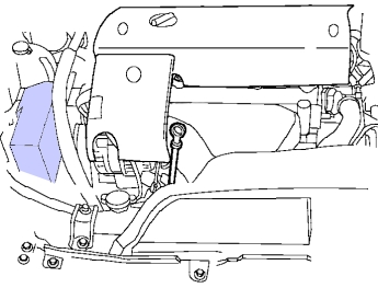
Diagram 2001-2002
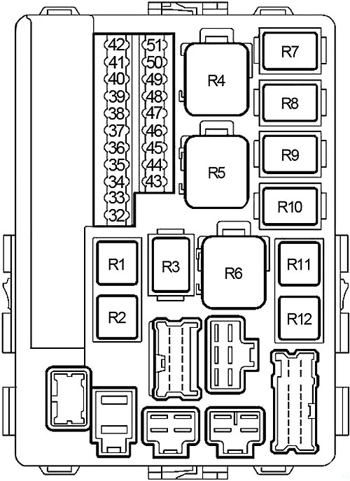
| № | A | Circuit Protected |
|---|---|---|
| 32 | 15 | Fuel Pump Relay |
| 33 | 10 | IPDM E/R CPU |
| 34 | 10 | Air Conditioner Relay |
| 35 | 20 | Rear Window Defogger Relay |
| 36 | 20 | Rear Window Defogger Relay |
| 37 | 15 | Throttle Control Motor Relay |
| 38 | 10 | Tail Lamp Relay (Parking Lamp, License Lamp, Tail Lamp) |
| 39 | 20 | Front Wiper Relay, Front Wiper Motor |
| 40 | 15 | IPDM E/R CPU |
| 41 | 15 | Fron Fog Lamp Relay |
| 42 | 10 | Transmission Control Module (TCM), Revolution Sensor, Turbine Revolution Sensor |
| 43 | - | - |
| 44 | 10 | EVAP Canister Purge Volume Control Solenoid Valve, EVAP Canister Vent Control Valve, Vacuum Cut Valve Bypass Valve, Intake Valve Timing Control Solenoid Valve, VIAS Control Solenoid Valve |
| 45 | 10 | ABS |
| 46 | 10 | Washer Motor |
| 47 | 10 | Headlamp High RH, Daytime Running Lights |
| 48 | 10 | Headlamp High LH, Daytime Running Lights |
| 49 | 15 | Headlamp Low LH |
| 50 | 15 | Headlamp Low RH |
| 51 | 15 | Engine Control Module Relay (ECM) |
| | ||
| R1 | Fuel Pump | |
| R2 | Air Conditioner | |
| R3 | Ignition | |
| R4 | Cooling Fan (№1 (Hi)) | |
| R5 | Cooling Fan (№2 (Hi)) | |
| R6 | Cooling Fan (№3 (Lo)) | |
| R7 | Headlamp Low | |
| R8 | Headlamp High | |
| R9 | Front Fog Lamp | |
| R10 | Starter | |
| R11 | Throttle Control Motor | |
| R12 | Engine Control Module | |
Diagram 2003-2006
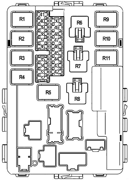
| № | A | Circuit Protected |
|---|---|---|
| 32 | 20 | Rear Window Defogger Relay |
| 33 | 10 | A/C Relay |
| 34 | 15 | IPDM E/R CPU |
| 35 | 15 | Engine Control Module (ECM), ECM Relay, NATS Antenna Amplifier |
| 36 | 15 | Headlamp Low LH |
| 37 | 20 | Rear Window Defogger Relay |
| 38 | 10 | Headlamp High LH, Daytime Running Lights |
| 39 | 20 | Front Wiper Relay |
| 40 | 10 | Headlamp High RH, Daytime Running Lights |
| 41 | 10 | Tail Lamp Relay (Parking Lamp, License Lamp, Tail Lamp) |
| 42 | 10 | EVAP Canister Purge Volume Control Solenoid Valve, EVAP Canister Vent Control Valve, Intake Valve Timing Control Solenoid Valve (VK35DE), VIAS Control Solenoid Valve (VK35DE) |
| 43 | 15 | Front Fog Lamp Relay |
| 44 | 15 | Throttle Control Motor Relay |
| 45 | 15 | Headlamp Low RH |
| 46 | 15 | Air Fuel Ratio Sensor, Heated Oxygen Sensor |
| 47 | 10 | Washer Motor |
| 48 | 10 | A/T PV Ignition Relay, Revolution Sensor, Turbine Revolution Sensor |
| 49 | 10 | ABS |
| 50 | 15 | Fuel Pump Relay |
| | ||
| R1 | Engine Control Module | |
| R2 | Headlamp High | |
| R3 | Headlamp Low | |
| R4 | Starter | |
| R5 | Ignition | |
| R6 | Cooling Fan (№1) | |
| R7 | Cooling Fan (№3) | |
| R8 | Cooling Fan (№2) | |
| R9 | Throttle Control Motor | |
| R10 | Fuel Pump | |
| R11 | Front Fog Lamp | |
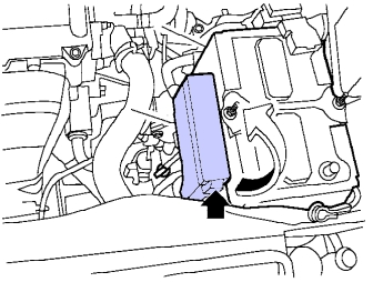
Engine Compartment Fuse Box №2
It is near the battery. Remove the fuse box cover by pushing the tab and lifting the cover up.
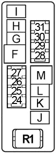
| № | A | Circuit Protected |
|---|---|---|
| 24 | 10 | 2001-2002: Engine Control Module, Immobilizer Control Module |
| 25 | 15 | Horn Relay |
| 26 | 10 | Generator |
| 27 | - | - |
| 28 | 10 | VQ35DE: Front Electronic Controlled Engine Mount, Rear Electronic Controlled Engine Mount |
| 29 | 15 | Heated Seat Relay |
| 30 | - | - |
| 31 | 15 | Audio |
| F | 50 | Body Control Module (BCM) |
| G | 30 | ABS |
| H | 30 | ABS |
| I | - | - |
| J | - | - |
| K | 40 | Cooling Fan Relay (№1, 2, 3) |
| L | 40 | Cooling Fan Relay (№1, 3) |
| M | 40 | Ignition Switch |
| | ||
| R1 | Horn | |
Fusible Link Block
It is located on the positive battery terminal.
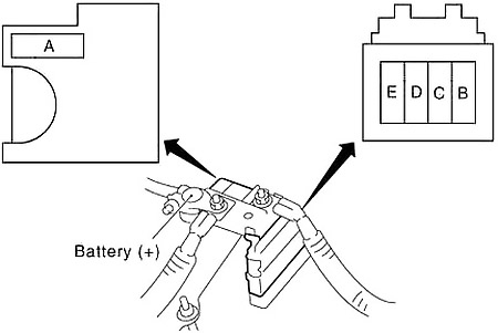
| № | A | Circuit Protected |
|---|---|---|
| A | 120 | Generator, Fuse: "D", "E" |
| B | 80 | 2001-2002: Ignition Relay (Fuse: "1", "12", "13", "14", "15", "32", "33", "42", "44", "45", "46"), Fuse: "35", "40", "51" |
| 80 | 2003-2006: Ignition Relay (Fuse: "42", "46", "47", "48", "49", "50"), Fuse: "33", "34", "35", "37" | |
| C | 60 | 2001-2002: Accessory Relay (Fuse: "5", "6", "7"), Blower Relay (Fuse: "10", "11"), Fuse: "19", "20" |
| 60 | 2003-2006: Accessory Relay (Fuse: "5", "6", "7"), Blower Relay (Fuse: "10", "11"), Fuse: "17", "19", "20", "21" | |
| D | 80 | 2001-2002: Headlamp High Relay (Fuse: "47", "48"), Headlamp Low Relay (Fuse: "49", "50"), Fuse: "34", "36", "37", "38", "39", "41" |
| 80 | 2003-2006: Headlamp High Relay (Fuse: "38", "40"), Headlamp Low Relay (Fuse: "36", "45"), Fuse: "32", "39", "41", "43", "44" | |
| E | 100 | 2001-2002: Fuse: 'D", "F", "G", "H", "L", "K", "M", "24", "25", "26", "28", "29" "31" |
| 100 | 2003-2006: Fuse: 'D", "L", "K", "M", "28", "29" "31" |
This website uses cookies to improve your experience. We'll assume you're ok with this, but you can opt-out if you wish. Cookie settingsACCEPT
Source: https://fusecheck.com/nissan/nissan-altima-2002-2006-fuse-diagram
Posted by: ferreridanayes.blogspot.com

Posting Komentar untuk "2003 Nissan Altima Ignition Switch Diagram"